Skip to content
 Every minute your production line sits idle, you’re losing money. Trying to identify gearbox without nameplate data can feel frustrating, but it shouldn’t stop you from getting back up and running. Nameplate loss is one of the most common challenges in industrial maintenance, but with the right approach, you can reverse engineer your gearbox specifications and find a compatible gearbox cross-reference and replacement speed reducer fast.
Quick Guide: How to Identify a Gearbox Without a Nameplate
- Identify the housing style (Inline, Right-Angle, Parallel, or Worm).
- Measure shaft diameters and center height using a digital caliper.
- Calculate the gear ratio by manually turning the input shaft.
- Check the connected motor for kW/HP and RPM data.
- Contact an engineer with photos for a quick cross-reference.
Follow these five steps to identify your gearbox model, gather the specs you need, and get back into production.
Step 1: Identify the Gearbox Type and Mounting Style
Start with what you can see. Walk up to the unit and observe its overall shape and configuration — this alone narrows your options significantly.
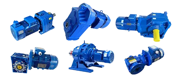
Gearbox types by geometry:
- Inline / Helical — Input and output shafts share the same axis; compact and cylindrical in appearance.
- Right Angle / Bevel-Helical — Output shaft runs perpendicular to the input; common in conveyor and mixing applications.
- Parallel Shaft — Input and output shafts run parallel but offset; typically a wider, flatter housing.
- Worm Gear — Compact right-angle unit with a crossed-axis worm and wheel; often used in lower-speed, higher-torque applications.
Mounting style:
- Solid Foot Mount — Bolted to a base plate via mounting feet on the housing.
- Flange Mount (B5 / B14) — Directly mated to a motor or machine frame via a flange face.
Step 2: Measure the Critical Dimensions
Grab a digital caliper and a measuring tape. Precise measurements are the foundation of any accurate cross-reference. Record the following:
- Output Shaft Diameter — Measure the shaft OD (outer diameter) in millimeters; common sizes include 25mm, 30mm, 35mm, 40mm, 50mm.
- Input Shaft Diameter — Same process on the motor-side shaft or hollow bore.
- Center Height — The vertical distance from the mounting foot base to the centerline of the output shaft; this is a key frame-size indicator.

- Flange Diameter (if applicable) — The outer diameter of the flange register (spigot); standard IEC sizes include 120mm, 160mm, 200mm, 250mm, 300mm, etc.
- Overall Housing Dimensions — Length × Width × Height of the gearbox body.
Cross-reference these measurements against IEC standard frame sizes (e.g., size 37, 47, 57, 67, 77, 87, 97 in the standard R/F/K/S naming convention). Even if the original brand is unknown, standard frame sizes are widely shared across manufacturers.
Stuck on measuring or don’t have the right tools? > Take 3-4 clear photos of your current setup and contact our engineering team . We’ll reverse-engineer the size for you within 2 hours.
Step 3: Calculate the Exact Gear Ratio
The gear ratio is often the hardest spec to recover — but there’s a simple hands-on method that requires zero special tools.
Manual counting method:
- Disconnect the gearbox from the load so the output shaft can spin freely.
- Mark both the input shaft and output shaft with a piece of chalk or tape.
- Slowly rotate the input shaft by hand and count how many full revolutions it takes for the output shaft to complete exactly one full revolution.
- That number is your gear ratio. If the input shaft turns 28.5 times per one output revolution, your ratio is i = 28.5:1.
Alternative method using motor speed:
If the gearbox is still connected to its original motor and the motor nameplate is intact, use this simple formula:
Formula: Gear Ratio (i) = Motor Speed (RPM) ÷ Output Speed (RPM)
Measure the output shaft speed with a tachometer or calculate it from the final driven equipment’s known operating speed. Divide motor RPM by output RPM to get your ratio.
Step 4: Check the Connected Motor Power
Good news: even when the power transmission drive’s nameplate is gone, the motor nameplate is almost always intact. The motor is your best secondary data source.
Record the following from the motor nameplate:
- Power rating — in kW or HP (e.g., 1.5 kW, 2.2 kW, 4 kW, 7.5 kW).
- Pole count / synchronous speed — 4-pole ≈ 1400–1450 RPM; 6-pole ≈ 950–960 RPM; 2-pole ≈ 2800–2900 RPM.
- Frame size — IEC (80, 90, 100, 112, 132, 160).
- Voltage and frequency — Confirms regional standard (50 Hz vs. 60 Hz).
Motor power directly informs the gearbox’s service factor and torque rating. A 4 kW motor at 1400 RPM driving through a 28.5:1 ratio produces a calculable output torque, which maps to a specific gearbox size class. This data alone can reduce a field of hundreds of possibilities down to two or three candidates.
Step 5: Let Our Engineers Identify It for You — In Under 2 Hours
If measuring feels tedious or you’re not confident in the readings, skip straight to this step.
Our technical team has extensive cross-reference experience with major industrial gearbox brands including SEW-Eurodrive, Flender, Nord, Bonfiglioli, Brevini, and more. We can identify an exact gear reducer equivalent — same mounting dimensions, same ratio, same torque rating — often at a significantly lower cost and faster lead time than the OEM.
Here’s all you need to send us:
- 3–4 clear photos (top, side, shaft end, and nameplate area even if blank)
- Output shaft diameter and center height (if you have them)
- Motor nameplate data (power, RPM, frame size)
- A brief description of the application (conveyor, mixer, extruder, etc.)
We’ll respond with a full cross-reference drawing and quotation within 2 business hours.
[Contact Our Engineering Team Now — Upload Your Photos]
Whether you’re replacing a legacy SEW R37 helical gearbox or tracking down an equivalent for an unlabeled unit, our team has the experience to get you the right part, fast.
FAQ:
Can I replace an SEW Eurodrive gearbox with a different brand?
Yes. Because industrial gearboxes often follow standard IEC frame sizes, cross-referencing to high-quality brands like ours is typically compatible. You get the exact same footprint and performance, often with much better lead times.
How do I find the ratio of a worm gear without a tag?
You can count the teeth on the bronze worm wheel and divide that number by the number of threads (starts) on the steel worm shaft. Alternatively, use the manual rotation method: turn the input shaft and count the rotations needed for one full output shaft rotation.
What if my input/output shaft size doesn’t match standard IEC sizes?
If you are dealing with legacy or proprietary equipment, don’t worry. We offer custom machining services and sleeve adapters to ensure a perfect fit for non-standard equipment, eliminating the need to modify your existing machine frame.